If wired according to the diagram it will work fine, but it isn't wired according to the diagram or it would work.

The batteries will perform better if wired together like the diagram I posted. Subtle difference but will equalize battery draw/charge slightly better. Not worth a major rewiring but looks simple enough to change from your photos.
Still not sure why they're disconnecting the Positive but it will work, of course. If the disconnect is on the Positive side you need to connect elevenity-seven wires to the switch so they're all switched. If the Negative is disconnected you only need one (1) wire to the switch and the other end to the trailer frame. If needed the Inverter negative can also be connected there for a grand total of two (2) wires there, not the mass of Pos wiring which is easily connected directly tothe battery. When working on any DC system the first step is to disconnect the Negative pole at the battery and a disconnect there does this with a switch.
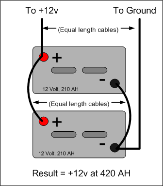
(As pointed out just above the cables leaving the battery need not be equal length. Diagram of convenience, nothing more.)
-- Chuck


 Linear Mode


