 |
|
 09-24-2019, 05:24 AM
|
#1
|
|
Senior Member
Join Date: Oct 2016
Location: Alaska
Posts: 1,830
|
My coach batteries stopped charging from the alternator. (Bad SDC-107A)
My coach batteries stopped charging from the alternator last month. I had to run the generator to charge my batteries when the sun wasn't shining. I found out I could start the generator at 8% on the Victron.
Finally after checking everything else, I pulled the cover off the SDC-107A to check the internal fuses. This is what I found:

I called to a RV Custom Products technician, today. The black hole is where the transistor that controls the BIRD was. I also learned a few thing about the SDC-107A.
- SDC-107A has only a is one year Warranty.
- Forest River no longer uses RV Custom Products. I do not know what replaced it. Maybe someone can tell me what BCC Forest River is installing now.
- RV Custom Products only sells a replacement COD with UPS.
- Cost:
$68.32 UPS ground freight is to Alaska.
$172.27 SDC-107A
$240.59 Total
I need to replace the SDC-107A as it powers the dash & radio.
The cover.

My first look at the damage with loose parts.

Blown Cap & transistor.

|

|

|
|
09-24-2019, 06:21 PM
|
#2
|
|
Senior Member
Join Date: Jan 2018
Posts: 605
|
Quote:
Originally Posted by rk06382

My coach batteries stopped charging from the alternator last month. I had to run the generator to charge my batteries when the sun wasn't shining. I found out I could start the generator at 8% on the Victron.
Finally after checking everything else, I pulled the cover off the SDC-107A to check the internal fuses. This is what I found:
I called to a RV Custom Products technician, today. The black hole is where the transistor that controls the BIRD was. I also learned a few thing about the SDC-107A.
- SDC-107A has only a is one year Warranty.
- Forest River no longer uses RV Custom Products. I do not know what replaced it. Maybe someone can tell me what BCC Forest River is installing now.
- RV Custom Products only sells a replacement COD with UPS.
- Cost:
$68.32 UPS ground freight is to Alaska.
$172.27 SDC-107A
$240.59 Total
I need to replace the SDC-107A as it powers the dash & radio.
The cover.
Attachment 215686
My first look at the damage with loose parts.
Attachment 215687
Blown Cap & transistor.
Attachment 215683 |
Good info. Thanks for sharing. I would be curious if a replacement would simply be a wire for wire swap.
__________________
2017 Georgetown GT3 31B3
N Little Rock AR
|
|
|
|
|
09-26-2019, 05:18 PM
|
#3
|
|
Senior Member
Join Date: Oct 2016
Location: Alaska
Posts: 1,830
|
I have the SDC-107A coming COD from RV Custom Products. It is scheduled to arrive Fri 9/27. (tomorrow)
I talked to Battle Born about using the stock BCC (SDC-107A) to charge the LiFePO4 batteries. One 100Ah LiFePO4 can be charged at 50 amps. Four 100Ah LiFePO4 batteries in parallel can be charged upto 200 amps. As the alternator is 178 amps, I am okay with the stock BCC.
I will be measuring Volts & Amps on the next trip to find out what is happening while the engine is on.
|
|
|
|
|
10-07-2019, 02:16 PM
|
#4
|
|
Senior Member
Join Date: Oct 2016
Location: Alaska
Posts: 1,830
|
Fri 9/27
The new SDC-107A from RV Custom Products arrived. After verifying that it is the correct part, I started taking pictures & documenting where each & every wire goes.
While checking each fuses inside the old SDC-107A, the only blown fuse was the 5 amp on the Aux Start circuit. (Emergency Start / battery boost)
See PDF: Forest River Forums - Downloads - FR3 Battery Control Center Schematic 5-31-16 11796
I also had to removed the Battle Born batteries as space in the battery compartment is limited. I wanted to see if I could find room for more Battle Born batteries. I also attached the chassis battery to the Victron BMV-712 shunt.
Mon 9/30 thru 10/4
Took one last trip before winterizing to the Kenai Peninsula.
It was cloudy so it was good that the alternator was recharging the batteries. I was able to measure 90 amps from the alternator. I watched voltage & amperage with the Victron BMV-712.
I noticed a problem with the BIRD (Bi-directional Isolator Relay Delay) relay. The BIRD stays latched longer because of the higher voltage of the Battle Born batteries. Relay latches at 13.2v & opens at 12.7v. My LiFePO4 batteries would be below 70% before the relay will stay open. When the relay is closed the LiFePO4 batteries will try to charge the chassis lead acid battery. I need to find out how to disable the BIRD relay when the engine is off.
Any thoughts?
See references below:
Quote from Custom RV's SDC-107A Battery Control Center (pdf): For the purpose of charging the coach and chassis batteries, power for the control electronics is obtained from the ignition switch and coach battery through diodes D1 and D2. Underway, when the charging source is the engine generator, +13.2vdc on the ignition line triggers the electronics. After a 15sec. delay, the interconnect relay closes, paralleling the batteries. Should the battery voltage go below 12.7vdc, the interconnect relay will open after around a 15sec. delay. When the vehicle is parked and on shore power, when the converter brings the coach battery up to +13.2vdc, the interconnect relay will close after the 15sec delay, charging the chassis battery as well. As before, the relay will open when the battery voltage goes below 12.7vdc. From Battle Born ( Comparison between one Battle Born LiFePO4 battery and two 6V GC2 batteries in series):
 Figure 3: Discharge curves: Voltage vs Capacity
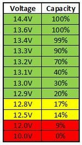 LiFePO4 State Of Charge, Voltage Chart
|
|
|
|
|
10-07-2019, 03:55 PM
|
#5
|
|
Senior Member
Join Date: Jan 2018
Posts: 605
|
I have a GT3 31B3 which is similar. Looking at your diagram I see a 5 AMP wire for your battery booster switch. I have a switch near the drivers seat but I do not have a 5 amp fused wire coming from that connection at the BCC. When I had issues with my alternator not charging I tried the battery boost switch and it had no affect. I am wondering if they put a switch in but did not connect it.
__________________
2017 Georgetown GT3 31B3
N Little Rock AR
|
|
|
|
|
10-07-2019, 04:50 PM
|
#6
|
|
Senior Member
Join Date: Oct 2016
Location: Alaska
Posts: 1,830
|
Quote:
Originally Posted by bclinton
I have a GT3 31B3 which is similar. Looking at your diagram I see a 5 AMP wire for your battery booster switch. I have a switch near the drivers seat but I do not have a 5 amp fused wire coming from that connection at the BCC. When I had issues with my alternator not charging I tried the battery boost switch and it had no affect. I am wondering if they put a switch in but did not connect it.
|
The fuse is inside the SDC-107A black box.

|
|
|
|
|
10-07-2019, 04:52 PM
|
#7
|
|
Senior Member
Join Date: Jan 2018
Posts: 605
|
Quote:
Originally Posted by rk06382
|
Ah! I see now. Thanks! I will give it a check!
__________________
2017 Georgetown GT3 31B3
N Little Rock AR
|
|
|
|
|
10-07-2019, 05:03 PM
|
#8
|
|
Senior Member
Join Date: Jul 2017
Location: California
Posts: 7,616
|
Personally, I would do what Sagecoachdriver does and manually turn on/off the circuit breaker near the alternator when deciding to charge the coach batteries when you don't have enough solar to charge them. That is the cheapest and easiest way to keep the Lithium from backfeeding the chassis battery.
Otherwise, I would use a dedicated DC to DC converter to charge the lithium batteries from the alternator.
|
|
|
|
|
10-07-2019, 06:03 PM
|
#9
|
|
Senior Member
Join Date: Oct 2016
Location: Alaska
Posts: 1,830
|
Quote:
Originally Posted by babock
Personally, I would do what Sagecoachdriver does and manually turn on/off the circuit breaker near the alternator when deciding to charge the coach batteries when you don't have enough solar to charge them. That is the cheapest and easiest way to keep the Lithium from backfeeding the chassis battery.
Otherwise, I would use a dedicated DC to DC converter to charge the lithium batteries from the alternator.
|
I just need to remove power from the relay when the engine is off. I can get 90 amps from the alternator but a Renogy 40 amp DC to DC Battery charger is $200.
|
|
|
|
|
10-07-2019, 06:22 PM
|
#10
|
|
Senior Member
Join Date: Jul 2017
Location: North of Seattle, WA
Posts: 17,330
|
Quote:
Originally Posted by rk06382
I just need to remove power from the relay when the engine is off. I can get 90 amps from the alternator but a Renogy 40 amp DC to DC Battery charger is $200.
|
Locate the control source for the relay and add another relay controlled by the ignition switch. Suitable relays for this are super inexpensive. Since you are merely switching a relay the current requirements are minimal. No need to run a separate power wire. Just use the new control wire from ignition switch, connected to both relay "coil" and one of the switched contacts. Other side of switched contact to control wire you cut on the charge relay.
Ignition on, board relay on. Ignition off, board relay off. Essentially the same as a manual switch but no forgetting.
Amazon has relays one could use for this in 2-packs for less than $10 to 10-packs for $15.
__________________
"A wise man can change his mind. A fool never will." (Japanese Proverb)
"You only grow old when you run out of new things to do"
2018 Flagstaff Micro Lite 25BDS
2023 f-150 SCREW XLT 3.5 Ecoboost (The result of a $68,000 oil change  )
|
|
|
|
|
10-07-2019, 08:05 PM
|
#11
|
|
Senior Member
Join Date: Jul 2017
Location: California
Posts: 7,616
|
I agree with the relay although you have another issue we haven't even talked about and that is your coach battery charging system, mainly solar, over charging your chassis battery. This could conceivably happen even with the engine running. If your BattleBorns are completely charged and sitting at 14.4V, you could easily overcharge your chassis battery.
|
|
|
|
|
10-07-2019, 08:12 PM
|
#12
|
|
Senior Member
Join Date: Oct 2016
Location: Alaska
Posts: 1,830
|
Quote:
Originally Posted by TitanMike
Locate the control source for the relay and add another relay controlled by the ignition switch. Suitable relays for this are super inexpensive. Since you are merely switching a relay the current requirements are minimal. No need to run a separate power wire. Just use the new control wire from ignition switch, connected to both relay "coil" and one of the switched contacts. Other side of switched contact to control wire you cut on the charge relay.
Ignition on, board relay on. Ignition off, board relay off. Essentially the same as a manual switch but no forgetting.
Amazon has relays one could use for this in 2-packs for less than $10 to 10-packs for $15.
|
I just need to inter-connect with the relay feed wire inside the black box.

I am going to contact RV Custom Products for advice.
|
|
|
|
|
10-09-2019, 05:12 PM
|
#13
|
|
Senior Member
Join Date: Oct 2016
Location: Alaska
Posts: 1,830
|
Quote:
Originally Posted by rk06382
I just need to inter-connect with the relay feed wire inside the black box.
Attachment 216814
I am going to contact RV Custom Products for advice. |
Reply from RV Custom Products: Cutting the white wire from the coach battery stud inside will do what you want.?? You will lose the ability to maintain your chassis battery when on shore power.?? To get around that, a small relay powered from coach battery through a switch would give you both functions but you would have to remember to throw the switch when you are on shore power extensively.?? The relay would be used to reconnect the white wire from the BIRD to coach battery. I took pictures of my old Burnt SDC-107A:

Removed a screw, bolt & two nuts.

White wire


Close up of burnt area


I have not looked at my new SDC-107A. But it will be difficult as the top right screw has a nut on the back for the red wire above. I may need to remove it from the RV to work on.
|
|
|
|
|
10-09-2019, 06:09 PM
|
#14
|
|
Senior Member
Join Date: Jul 2017
Location: California
Posts: 7,616
|
Another thing you can do is to add a diodes in series in the wire that detects the voltage of the coach batteries. That will bring the voltage down in the sense circuit to fool it to make the coach batteries look like they are below the "charging" threshold.
Again, I think you should just completely isolate the lithium from being charged from the chassis unless you find yourself in a situation where you have not had enough solar to charge them. Then it would just be an emergency situation.
So...what was that component that burnt up? If it was a relay that is trying to pass charge current to your lithium batteries, it's going to have an issue because of the lithiums ability to charge with a huge amount of current.
|
|
|
|
|
10-10-2019, 07:52 PM
|
#15
|
|
Senior Member
Join Date: Oct 2016
Location: Alaska
Posts: 1,830
|
Quote:
Originally Posted by babock
another thing you can do is to add a diodes in series in the wire that detects the voltage of the coach batteries. That will bring the voltage down in the sense circuit to fool it to make the coach batteries look like they are below the "charging" threshold.
Again, i think you should just completely isolate the lithium from being charged from the chassis unless you find yourself in a situation where you have not had enough solar to charge them. Then it would just be an emergency situation.
So...what was that component that burnt up? If it was a relay that is trying to pass charge current to your lithium batteries, it's going to have an issue because of the lithiums ability to charge with a huge amount of current.
|
What burned was the control electronics that controlled the big interconnect relay.

|
|
|
|
|
10-18-2019, 04:53 AM
|
#16
|
|
Senior Member
Join Date: Oct 2016
Location: Alaska
Posts: 1,830
|
I have been in email communication with John Mock. (RV Custom Products)
- I could disable the interconnect relay for coach to chassis while parked, by cutting the white wire, but that would disable charging of the chassis battery.
"When the vehicle is parked and on shore power the converter brings the coach battery up to +13.2 vdc, the interconnect relay will close after the 15 sec delay, charging the chassis battery as well. The relay will open when the battery voltage goes below 12.7 vdc."
- I asked John if I could change voltage settings of the BCC. He said I could try by turning the potentiometer clockwise to increases the trip voltage. I don't know how far it will go. It is worth a try.
"A better approach would be to use the same adjustment we use to calibrate the electronics.?? We put 13.2v on the unit and adjust the potentiometer in the upper left corner of the board until the comparator just trips.?? Since there is a delay between the trip point and relay pull in, we measure the voltage on the test point (the 1/8in. pad at the upper right corner of the potentiometer.?? At trip, the test point goes high around 12.5v and when the drop out point (12.7v) is reached, the test point drops to around 0.1v.?? If the pot were to be adjusted to 14.2v, the drop out point would probably be 13.6v ( the normal difference 0.5v will increase slightly as the trip point is raised).??
Your converter output must exceed the trip point for this to work.?? I don't know how high the pot will go." John Mock


I don't know how soon I can try this as the FR3 is winterized. I will practice on the old burnt circuit board.
|
|
|
|
|
10-23-2019, 04:30 AM
|
#17
|
|
Senior Member
Join Date: Oct 2016
Location: Alaska
Posts: 1,830
|
How to adjust SDC-107A BCC for Battle Born batteries

For the voltage measurements below I used both my Victron BMV-712 & a multimeter. - Victron BMV-712 monitored both the Battle Born house batteries & the chassis (starter) battery.
- Multimeter monitored the testpoint 'voltage drop out point.'
Quote:
John Mock @ RV Custom Products
Tue 10/15/2019 10:15 PM :: "A better approach would be to use the same adjustment we use to calibrate the electronics. We put 13.2v on the unit and adjust the potentiometer in the upper left corner of the board until the comparator just trips. Since there is a delay between the trip point and relay pull in, we measure the voltage on the test point (the 1/8in. pad at the upper right corner of the potentiometer. At trip, the test point goes high around 12.5v and when the drop out point (12.7v) is reached, the test point drops to around 0.1v. If the pot were to be adjusted to 14.2v, the drop out point would probably be 13.6v ( the normal difference 0.5v will increase slightly as the trip point is raised)."
Thu 10/17/2019 4:03 PM :: "That is the test point. Clockwise on the pot increases trip voltage. Don't know how far it will go.
Your converter output must exceed the trip point for this to work. I don't know how high the pot will go."
|
Using the directions above, I was able to adjust the BCC BIRD trip voltages.
First I cleaned off the paint from the potentiometer and took a picture: Potentiometer at 2 O'clock 
Next I disconnected shore power and all battery chargers. IE: Inverter/Charger & Solar Charge Controller.
I used a multimeter to measure the voltage at the test point.

I could only lower the battery voltage by turning on the headlights.
The Battery voltage started at 13.6v after the charger was shut off. I turned the potentiometer clockwise until the voltage dropped. Ten seconds later the relay opened with a clunk. I then turned the charger back on until the the relay closed again. I was not able to tell what the voltage was as it rose too fast. It looked like it was about 14v.
I turned the potentiometer counterclockwise alittle and turn the charger off again. As the voltage dropped I measure the voltage on both Victron BMV-712 & a multimeter at the test point. When the test point drop out point, the Victron BMV-712 read about 13.5v.

I repeated the process of charging until the relay closed & discharging utli it opens. When it opened at about 13.45v, I stopped.

I started the engine & watched the voltage rise & relay close at about 13.9v.
The after picture of the potentiometer: Potentiometer at 4 O'clock 
I repeated the process, and remeasured the voltage points that the relay opened & closed. see the graph below:

Conclusion: 
I am happy with the results. The SDC-107A BCC is now safe to use with my Battle Born batteries. I have isolation when there is no charger raising the voltage above 14v.
Also, I noticed that when my Battle Born batteries were below 50%, I could get about 140 amps from the alternator. Which means a Class A or C install of Battle Born batteries should be a minimum of three to support the 140 amp.
Thanks
|
|
|
|
|
10-23-2019, 12:21 PM
|
#18
|
|
Senior Member
Join Date: Jul 2017
Location: California
Posts: 7,616
|
Quote:
Originally Posted by rk06382
Also, I noticed that when my Battle Born batteries were below 50%, I could get about 140 amps from the alternator. Which means a Class A or C install of Battle Born batteries should be a minimum of three to support the 140 amp.
Thanks
|
You worried at all about running your alternator @140A with 100% duty cycle?
|
|
|
|
|
10-23-2019, 01:18 PM
|
#19
|
|
Senior Member
Join Date: Oct 2016
Location: Alaska
Posts: 1,830
|
Quote:
Originally Posted by babock
You worried at all about running your alternator @140A with 100% duty cycle?
|
The Battle Born batteries have a 50 amp limit per batteries. Two batteries are 100 amp. IE: three=150 amp. The 50 amp limit is controlled by the Battle Born BMS inside each battery. I do not want to stress the BMS.
When I talked to Battle Born recommend the LiFePO4 Battery Isolation Manager (BIM) for two batteries.

Side note: The above BIM disconnects at 13.4v.
Quote:
|
If the coach battery resting voltage exceeds 13.4V than the BIM will disconnect. A resting voltage greater than 13.4V indicates a fully charged battery. Note that resting voltage means that no current is flowing to the coach battery.
|
|
|
|
|
|
10-23-2019, 01:35 PM
|
#20
|
|
Senior Member
Join Date: Jul 2017
Location: California
Posts: 7,616
|
I am not asking about the batteries...I am talking about the alternator. The isolation manager that BB recommends would at least reduce the duty factor for your alternator. It never allows 100% duty cycle.
|
|
|
|
|
|
| Thread Tools |
|
|
| Display Modes |
 Linear Mode Linear Mode
|
 Posting Rules
|
You may not post new threads
You may not post replies
You may not post attachments
You may not edit your posts
HTML code is Off
|
|
|
|
 » Recent Discussions
 |
|
|
|
|
|
|
|
|
|
|
|
|
|
|
|
|
|
|
|
|
|
|
|
|
|
|
|
|
|
|
|
|
|


 2018 FR3 28DS | Boondock 99% of the time


