 |
|
 04-14-2016, 06:16 PM
|
#1
|
|
Senior Member
Join Date: Mar 2016
Posts: 139
|
Shunt connection question
I couldn't find an answer...

The connections shown are my batteries. I will be connecting the ground from the charger here as well, which is being located in the front storage compartment. The existing ground runs to the frame which will take the 4th spot on the bar.
Am I right in that my shunt will go between the bus bar and the chassis ground? There currently is no ground running from the batteries back to the panel nor will there be one from the relocated charger back to the panel. At least not yet.
|

|

|
|
04-14-2016, 06:46 PM
|
#2
|
|
Senior Member
Join Date: Jan 2015
Location: Englewood FL
Posts: 2,797
|
Quote:
Originally Posted by opie

I couldn't find an answer...

The connections shown are my batteries. I will be connecting the ground from the charger here as well, which is being located in the front storage compartment. The existing ground runs to the frame which will take the 4th spot on the bar.
Am I right in that my shunt will go between the bus bar and the chassis ground? There currently is no ground running from the batteries back to the panel nor will there be one from the relocated charger back to the panel. At least not yet. |
If you connect the charger to the batteries directly (i.e. not through the shunt) the system will not "see" the recharge current and not be able to calculate the net charge on the batteries. The charger ground needs to go to the chassis so that the charging current will also go through the shunt and not around it.
__________________
 2015 335DS
|
|
|
|
|
04-14-2016, 06:56 PM
|
#3
|
|
Senior Member
Join Date: Mar 2016
Posts: 139
|
Quote:
Originally Posted by ScottBrownstein
If you connect the charger to the batteries directly (i.e. not through the shunt) the system will not "see" the recharge current and not be able to calculate the net charge on the batteries. The charger ground needs to go to the chassis so that the charging current will also go through the shunt and not around it.
|
It will go to the chassis via the distribution bar.....
1 line coming from the existing chassis ground to the distribution bar... Then both batteries and charger grounds go to distribution bar.
I think I just answered my own question.... Or did I?
|
|
|
|
|
04-14-2016, 06:59 PM
|
#4
|
|
Senior Member
Join Date: Jan 2015
Location: Englewood FL
Posts: 2,797
|
Quote:
Originally Posted by opie
It will go to the chassis via the distribution bar.....
1 line coming from the existing chassis ground to the distribution bar... Then both batteries and charger grounds go to distribution bar.
I think I just answered my own question.... Or did I?
|
The charger negative has to go through the shunt. If it doesn't the shunt will not measure the charger current. If you put it on the buss bar and disconnect the chassis ground from the shunt, the charger will charge anyway since it can get to the battery negative. This means that the shunt can't see that current and this will mean that your meter cannot see it either.
__________________
2015 335DS
|
|
|
|
|
04-14-2016, 07:09 PM
|
#5
|
|
Senior Member
Join Date: Mar 2016
Posts: 139
|
Quote:
Originally Posted by ScottBrownstein
The charger negative has to go through the shunt. If it doesn't the shunt will not measure the charger current. If you put it on the buss bar and disconnect the chassis ground from the shunt, the charger will charge anyway since it can get to the battery negative. This means that the shunt can't see that current and this will mean that your meter cannot see it either.
|
BTW, I'm dense so I apologize now. Thank you for taking the time to spell this out for me.
So if I'm reading you right, my negative wiring needs to go...
Black from charger, to shunt, to buss bar.... and from buss bar to batteries and chassis ground.
|
|
|
|
|
04-14-2016, 07:33 PM
|
#6
|
|
Senior Member
Join Date: Jan 2015
Location: Englewood FL
Posts: 2,797
|
Quote:
Originally Posted by opie
BTW, I'm dense so I apologize now. Thank you for taking the time to spell this out for me.
So if I'm reading you right, my negative wiring needs to go...
Black from charger, to shunt, to buss bar.... and from buss bar to batteries and chassis ground.
|
OK...but it needs to go on the FAR side of the shunt, away from the bus bar and on the same side of the shunt as the chassis ground connection.
__________________
2015 335DS
|
|
|
|
|
04-14-2016, 07:51 PM
|
#7
|
|
Senior Member
Join Date: Mar 2016
Posts: 139
|
Quote:
Originally Posted by ScottBrownstein
OK...but it needs to go on the FAR side of the shunt, away from the bus bar and on the same side of the shunt as the chassis ground connection.
|
Getting close...
So I only want my batteries connected to the buss bar....
If I eliminate the buss bar, just using the shunt, I would have the charger and chassis ground on one post and my 2 battery negatives on the other, right....
|
|
|
|
|
04-15-2016, 05:44 AM
|
#8
|
|
Senior Member
Join Date: Jan 2015
Location: Englewood FL
Posts: 2,797
|
Quote:
Originally Posted by opie
Getting close...
So I only want my batteries connected to the buss bar....
If I eliminate the buss bar, just using the shunt, I would have the charger and chassis ground on one post and my 2 battery negatives on the other, right....
|
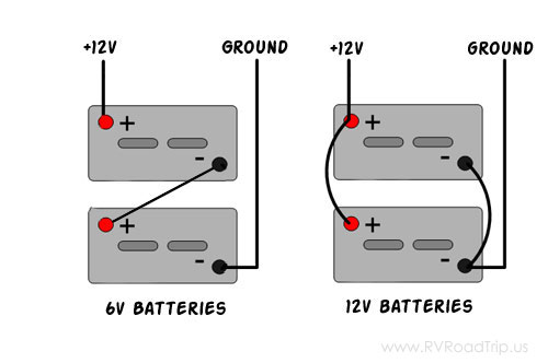
Yep. Technically that would do it, presuming that you mean the "posts" of your shunt. However, I assume that they are 12 volt, so battery number one's positive post has the load from the coach and a short positive wire to battery number two's positive post. You should run a negative to the shunt from battery number two's negative post and a short negative from that post to the negative on battery number one.. That way both batteries have equal length cables, one with a short red to the other and the second with a short black.
This way both batteries see equal load and equal charge with one having a shorter negative path and the other having a shorter positive path. Like the 12 volt in the diagram.
__________________
2015 335DS
|
|
|
|
|
04-15-2016, 05:46 AM
|
#9
|
|
Senior Member
Join Date: Mar 2016
Posts: 139
|
Quote:
Originally Posted by ScottBrownstein
Yep. that will do it. Presuming that you mean the "posts" of your shunt.
|
Yes.
Thanks again.
Sent from a field
|
|
|
|
|
04-15-2016, 06:26 AM
|
#10
|
|
Senior Member
Join Date: Mar 2016
Posts: 1,060
|
Wiring Diagram
The shunt goes in the negative wiring between the battery bank and the negative bus bar. See image from a website explaining. Send me a PM for additional info.
|
|
|
|
|
04-15-2016, 07:09 AM
|
#11
|
|
Senior Member
Join Date: Jan 2015
Location: Englewood FL
Posts: 2,797
|
Quote:
Originally Posted by 25FKS
The shunt goes in the negative wiring between the battery bank and the negative bus bar. See image from a website explaining. Send me a PM for additional info.
|
Agree. In your case, the negative buss bar is the chassis!
__________________
2015 335DS
|
|
|
|
|
04-15-2016, 07:29 AM
|
#12
|
|
Senior Member
Join Date: Mar 2016
Posts: 1,060
|
I love people speaking for me. No I will have actual bus bars (and set up) as shown in the diagram. I will have a connection f(wire) rom the bus bar to the chassis to enable FR wired items using the chassis as the negative BB.
I do a lot of work in the marine industry that has a chassis made of "plastic". No shortcuts there. All wiring is connected in "complete" circuits vs using a chassis for a negative backbone.
Again, once I finally pick up my TT (Next Month - Yeah!), I'll post pics.
|
|
|
|
|
04-15-2016, 07:48 AM
|
#13
|
|
Senior Member
Join Date: Jan 2015
Location: Englewood FL
Posts: 2,797
|
Quote:
Originally Posted by 25FKS
I love people speaking for me...
|
No, I wasn't speaking for you...I was trying to avoid confusing the OP who was going to put in bus bars but now will not need them for installing his shunt, which was the subject of his original post. You are kinda late to this thread.
__________________
2015 335DS
|
|
|
|
|
04-15-2016, 07:56 AM
|
#14
|
|
Senior Member
Join Date: Mar 2016
Posts: 1,060
|
No offense taken, but I was hardly late - my reply was on page 1. I was just trying to provide an overall picture on "how to do" to make it easier to visualize for those less familiar with the concepts.
|
|
|
|
|
04-15-2016, 09:17 AM
|
#15
|
|
Senior Member
Join Date: Mar 2016
Posts: 139
|
Quote:
Originally Posted by ScottBrownstein
Yep. Technically that would do it, presuming that you mean the "posts" of your shunt. However, I assume that they are 12 volt, so battery number one's positive post has the load from the coach and a short positive wire to battery number two's positive post. You should run a negative to the shunt from battery number two's negative post and a short negative from that post to the negative on battery number one.. That way both batteries have equal length cables, one with a short red to the other and the second with a short black.
This way both batteries see equal load and equal charge with one having a shorter negative path and the other having a shorter positive path. Like the 12 volt in the diagram.
|
I am using 6 volt Batts and wiring them up as 2 banks of 12 volt. Using a 1,2,both disconnect to make the parallel connection.
My interconnects are the same length. My positives from each bank to the switch are equal and my negatives which will go to the shunt are equal. I'm also going to make the pos. and neg. from the charger equal length.
Sent from a field
|
|
|
|
|
04-15-2016, 09:19 AM
|
#16
|
|
Senior Member
Join Date: Jan 2015
Location: Englewood FL
Posts: 2,797
|
Perfect...you have it down pat now.
__________________
2015 335DS
|
|
|
|
|
04-15-2016, 07:42 PM
|
#17
|
|
Senior Member
Join Date: Mar 2016
Posts: 139
|
Success.


Ran out of daylight and the boy has a recital tomorrow morning so I didn't get the trimetric hooked up. Tomorrow after I spray for mosquitos.
Sent from a field
|
|
|
|
|
04-16-2016, 06:32 AM
|
#18
|
|
Senior Member
Join Date: Mar 2016
Posts: 1,060
|
Just like in a chain or tug of war, the weakest link is the source of problems. You have different size wires. They should all be the same AWG. The red positive ones going to the switch and the red positive out of the switch as well as the black negative ones. Also, use as little length as possible - turn both small positives 180 and probably reduce their length 50%.
|
|
|
|
|
04-16-2016, 07:17 AM
|
#19
|
|
Senior Member
Join Date: Jan 2015
Location: Englewood FL
Posts: 2,797
|
Have made this point countless times. Why use 2/0 between the batteries if you use #4 or 6 from the batteries to the loads? It won't hurt, but it won't help much either. Shorter the better but then it is probably 15 feet or more to the load anyway, so what difference does another 6 inches make?
__________________
2015 335DS
|
|
|
|
|
04-16-2016, 08:25 AM
|
#20
|
|
Senior Member
Join Date: Mar 2016
Posts: 1,060
|
Like wise. I will not get into arguments. The point of Forums is to help, learn, ... never have ____ contests. I have had nothing but constant _____ since I joined. If this continues every time I post helpful ideas, I'll just stop assisting anyone anymore. I have 40 years experience doing this - take it or leave it, but keep disagreements off unless there is a valid reason, especially if one is not the original poster.
Like politics the relied on foundation is wrong to start with - if the wires are sized too small too (4, 6 awg), then they should be changed/upgraded too. Just because the windows leak air is no reason to not fix a leaky door first or in addition.
I do not know what the factory wiring is internally or user modifications have been done by members, but using the Famp rule, the proper size wire awg can be determined. In DC wiring proper size is CRITICAL! In AC too , but there is more leeway due to lower currents involved.
I have asked the factory for an electrical wiring diagram for my TT, but have been met with gigantic resistance to provide anything. This is a major flaw in their customer relations. I'll be sure to reemphasize this at some point. Heck the inverter, generator, .... everthing I've installed in a ________ has come with wiring schematics & drawings. This is a first for me.
|
|
|
|
|
|
 Posting Rules
|
You may not post new threads
You may not post replies
You may not post attachments
You may not edit your posts
HTML code is Off
|
|
|
|
 » Recent Discussions
 |
|
|
|
|
|
|
|
|
|
|
|
|
|
|
|
|
|
|
|
|
|
|
|
|
|
|
|
|
|
|
|
|
|


 Linear Mode

